|
ECU Installation pages ECU Installation home |
US OBD I ECUs
This series of computers has the ROM and microprocessor combined.
Circuitry needs to be added to run an external ROM. Part locations and
numbers and orientation are clearly printed in the circuit board.
1. Desolder all holes for the components.
2. Solder in a 28 pin socket.
3. Solder in the 74HC373.
4. Solder a 1.1K ohm resistor into R54 location marked in white lettering
(not needed on P72).
5. Solder in two 0.1uF ceramic disc capacitors into C51 and C52.
6. Solder in J1. This jumper can activated by utilizing an unused resistor
lead or extra section of spare wire.
7. Insert the 28 pin DIP ROM in the proper orientation and start the car.
Cut J1 to return the ECU to stock.
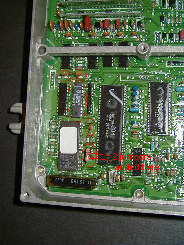
pictures courtesy of Jason Katman/FF-SQUAD.COM .