|
ECU Installation pages ECU Installation home |
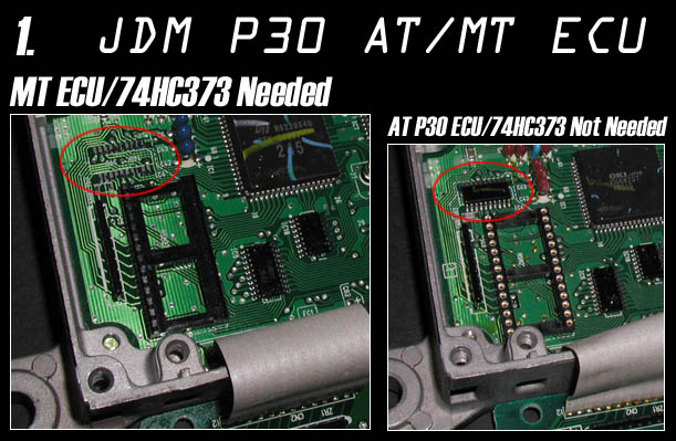
JDM OBD I ECUs
This series of ECUs is about 2/3 the size of the US ECUs and uses
mostly surface mount technology. This series of computers also has
the ROM and microprocessor combined. A fine tipped soldering iron
and lots of soldering experience is needed to install the surface
mounted 74HC373 chip.
1. Desolder all holes for the components.
2. Solder in a 28 pin DIP thru-hole type ROM socket.
3. Solder in the 74HC373 SMD Chip. If the the IC chip is the wide
package type you need to bend the leads to line up. Use flux when
soldering. Pin one is at the lower right hand corner in the diagram.
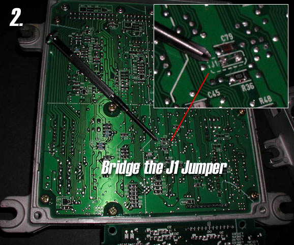
4. Solder in J1. This jumper can activated by utilizing an unused resistor lead or
extra section of spare wire. This location is on the backside of the ECU
motherboard.
5. Insert 28 pin DIP ROM in the proper orientation and start the
car.
Caution: If you plug in an EPROM or EEPROM backwards it will overheat
and erase or damage the device.
Cut J1 to return the ECU to stock.
pictures courtesy of Jason Katman/FF-SQUAD.COM .